SysMLv2 Modeling with the Free OSS Tool SysON (6) – Creating ActionFlows
Back to TopTo reach a broader audience, this article has been translated from Japanese.
You can find the original version here.
In the previous article, we created Action Definitions and Action Usages.
In this article, we'll use those to create an ActionFlow.
SysMLv2 provides a standard ActionFlowView for displaying connections between Actions. It would be natural to use this ActionFlowView to create an ActionFlow. However, on the Action Flow View page in the SysON documentation, it is marked as "under development". This was the case not only in v2025.8.0 used throughout this series, but also in the current main branch at the time of writing.
Therefore, this time we'll create an ActionFlow within an element's Graphical Compartment. A Graphical Compartment is a section within a Part or Action frame where a graphical view can be displayed.
In this article, we mainly introduce the creation flow. For operational details like how to add elements, please refer to the previous articles in this series.
Creating an Action Flow (Part 1)
#Let's create the diagram from slide 30 of "Introduction to the SysML v2 Language Textual Notation".
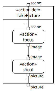
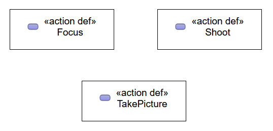
Open the General View and create three Action Definitions. Rename the created Action Definitions to "Focus", "Shoot", and "TakePicture", respectively.
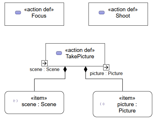
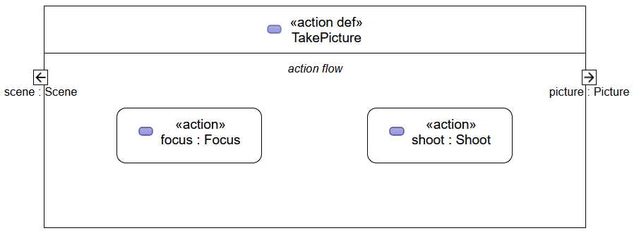
Add one input Item and one output Item to "TakePicture". Rename the input Item to "scene : Scene" and the output Item to "picture : Picture".
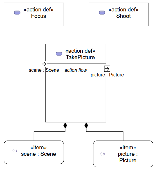
Open the Manage Visibility context menu for "TakePicture" and turn on the "action flow" checkbox. This displays the Graphical Compartment for showing the Action Flow View in "TakePicture".
Right-click the action flow compartment in "TakePicture" and create two Action Usages from the context menu. Rename the created Action Usages to "focus : Focus" and "shoot : Shoot", respectively.
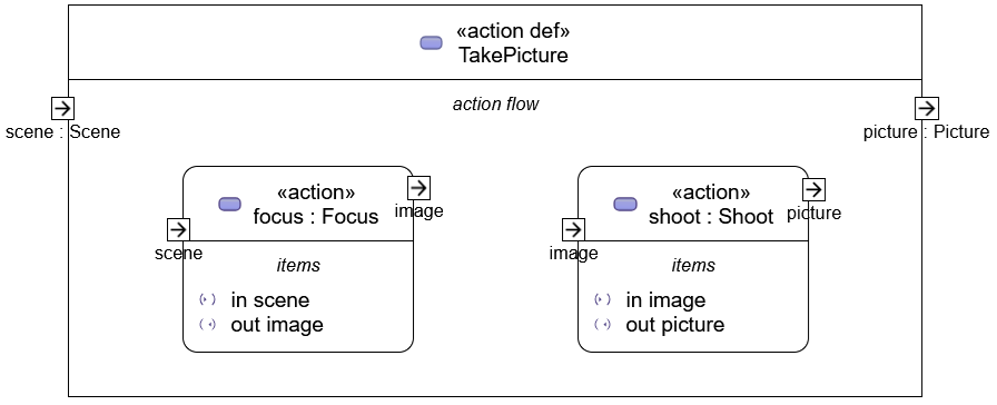
Add one input Item and one output Item to the Action Usage "focus". Rename the input Item to "scene" and the output Item to "image". Similarly, add one input Item and one output Item to the Action Usage "shoot". Rename the input Item and output Item to "image" and "picture", respectively.
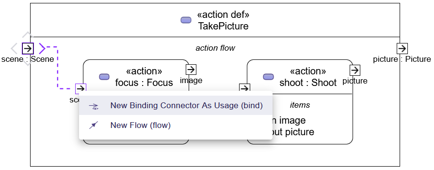
Select the input Item "scene" in "TakePicture". Drag the ">" displayed outside and drop it on the input Item of "focus" to display a menu for selecting the connection type. From the menu, select "New Binding Connector As Usage (bind)".
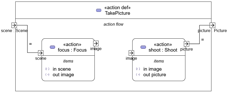
A line (connector) connecting the two Items will be added. Also, an "=" symbol appears near this connector. This is a Binding Connection.
Similarly, connect the output Item of the Action Usage "shoot" and the output Item of "TakePicture", which is "picture", with a connector.
Now connect the output Item of "focus" and the input Item of "shoot". Again, drag & drop to bring up the menu for selecting the connection type, but this time choose "New Flow (flow)" from the menu. A line with an arrow on one end is added. This is a Flow Connection.
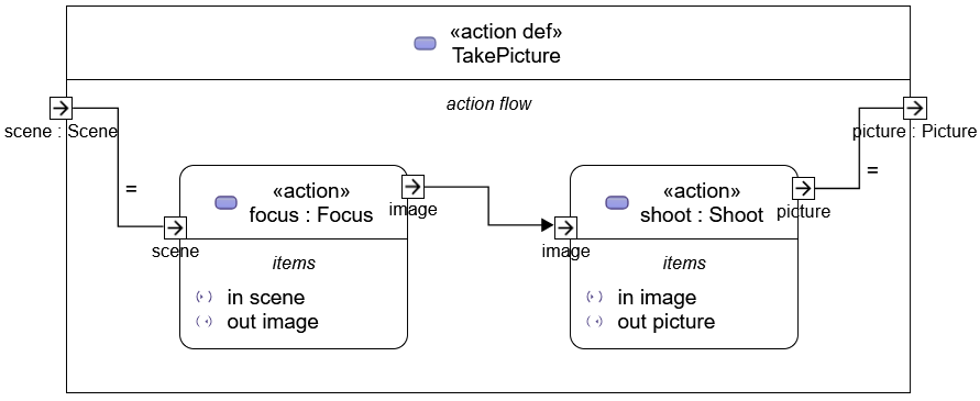
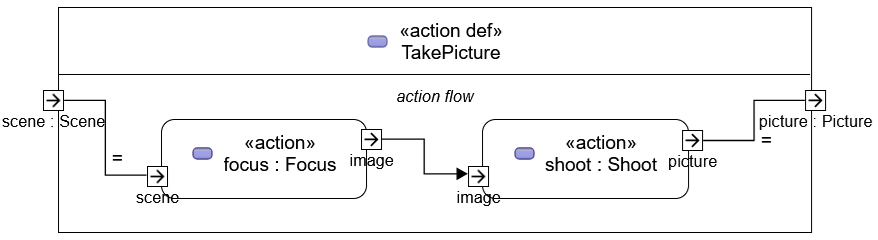
Hiding any unnecessary elements completes the diagram.
Creating an Action Flow (Part 2)
#This time, we'll create another diagram.
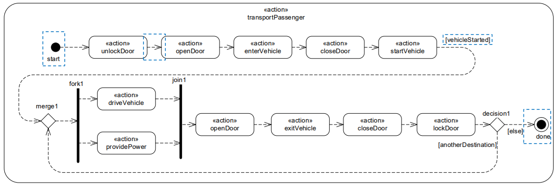
It's the diagram from slide 58 of "Intro to the SysML v2 Language-Graphical Notation.pdf". It uses several Control Nodes such as branching and merging.
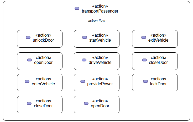
Open the General View and add an Action Usage. Rename the added Action Usage to "transportPassenger".
In the Manage Visibility for "transportPassenger", check "action flow". Add Action Usages to the displayed action flow compartment. Add 11 Action Usages according to the example and rename each one.
Right-click the action flow compartment, and from the "Behavior" section of the context menu, add the required Control Nodes.
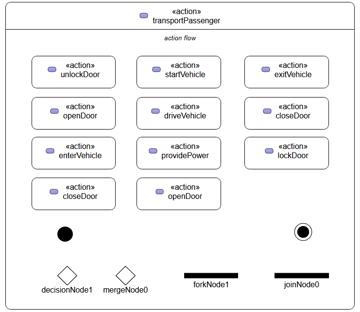
It seems that you cannot change the size of Decision Nodes or Merge Nodes, or make Fork Nodes or Join Nodes vertically elongated.
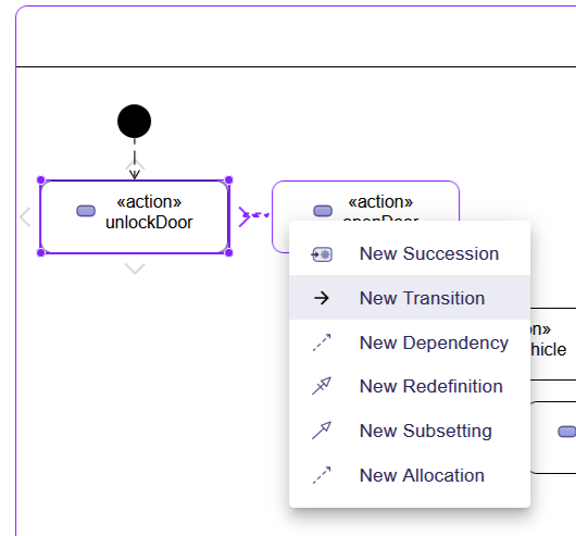
When selecting a Control Node or Action Usage, drag & drop the ">" displayed outside to connect them in the flow. When connecting, select "New Transition" from the context menu.
We managed to rearrange the elements in the action flow and write the flow.
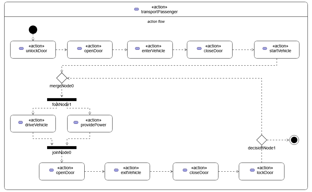
We would finish the diagram by adding guards, but we couldn't find this procedure.
Creating an Action Flow with the Text Notation
#Using the text notation, you can also add guard conditions.
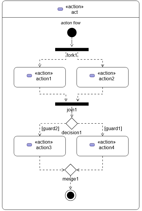
Based on the text notation listed in the table on p. 92 of the SysMLv2 specification, I created the following. Since guards must be Boolean, I added them as attributes. I changed "terminate" to "done" because "terminate" is not displayed.
action act {
	attribute guard1 : ScalarValues::Boolean;
	attribute guard2 : ScalarValues::Boolean;

	first start;
	then fork fork1;
		then action1;
		then action2;
	action action1;
		then join1;
	action action2;
		then join1;
	join join1;
	then decide decision1;
		if guard2 then action3;
		if guard1 then action4;
	action action3;
		then merge1;
	action action4;
		then merge1;
	merge merge1;
	then done;
}
Feeding this into SysON to generate objects and then displaying and formatting it in the General View results in the following figure.
Summary and Next Preview
#The SysMLv2 specification contains other examples of Action Flows as well. Also, the document that serves as the theme of this series includes additional Action Flows beyond the ones mentioned above. However, in the version of SysON used in this series, it is not possible to represent all of these Action Flows using the graphical notation. On the other hand, the GitHub commit logs show that SysON is being actively developed on a daily basis. Let's look forward to future releases, including the Action Flow View.
Next time, we will create State Definitions and State Usages. I believe State is still under development as well, but let's see how far we can go.